
Ballooned Drawing
Ballooned Drawing is an annotated design drawing whose unique characteristic identifiers connect applicable requirements and feature occurrences with an inspection accountability register.

On this page · 10 sections
- 1Ballooned Drawing
- 2Extract dimensions, notes and inherited requirements
- 3Separate balloon IDs from occurrence coverage
- 4Build the accountability register and evidence links
- 5Worked example: BD-247 housing, revision E
- 6Worked revision decision: BD-247 from E to F
- 7Standards context and jurisdiction-specific applicability
- 8Exchange register data and recover exceptions
- 9Recognize coverage failures before review
- 10Resolve crowded leaders and overlapping note applicability
How does Ballooned Drawing apply to your shop floor?
Pick your industry and scale — Ask V5 rewrites the definition in your context, gives a worked example, and shows what V5 does on day one.
01Ballooned Drawing
What a ballooned drawing identifies
A Ballooned Drawing is a design drawing annotated with unique identifiers that link specified characteristics to an accountability or inspection register and the evidence used to assess them.
Also called a balloon drawing or numbered characteristic drawing, it provides a shared reference between design information and assessment results. The balloon is the visible identifier beside a dimension, feature or note. The register carries the requirement, source location, applicability and evidence relationship; the annotation alone does not explain whether the requirement has been satisfied.
| Term | Main function | Relationship to ballooning |
|---|---|---|
| Engineering drawing | Defines design requirements. | Provides the source content being identified. |
| Ballooned drawing | Visibly identifies specified characteristics. | Connects drawing locations to register entries. |
| Characteristic register | Organizes requirement accountability. | Connects identifiers, applicability and evidence references. |
| Inspection report | Records inspection results. | Provides results associated with identified characteristics. |
| First article inspection | Assesses initial production against design requirements. | Uses characteristic accountability within a broader assessment process. |
These are practical document distinctions, not a universal mandated format. A register may be separate from the inspection report or combined with it, provided the requirement-to-result relationship remains clear. The inspection record addresses the evidence itself; ballooning addresses which characteristic that evidence concerns.
The principal boundary is authority: ballooning organizes characteristic accountability. It does not approve the engineering drawing, determine revision effectivity, replace the overall FAI process or authorize product release. Those decisions belong to the applicable engineering and quality assurance process, not to the presence of numbered circles.
02Extract dimensions, notes and inherited requirements
Treat extraction as a controlled reading of the design, not simply a search for dimension labels. The following proposed method keeps the requirement separate from the inspector’s interpretation; actual interpretation follows the applicable drawing conventions and authorized technical decisions.
- Identify the drawing number, revision and associated sheets or model references. Establish which design documents belong together before extracting individual requirements.
- Examine every view, section and detail. Record where a requirement originates and where another view helps explain its location or extent.
- Read dimensions and feature-control frames together with their associated geometry. Preserve modifiers, datum references and relationships rather than copying only the nominal value.
- Inspect title-block conventions for units, general tolerances and interpretation rules. Record their stated scope instead of assuming they apply to every drawing entry.
- Review local and general notes, including material, finish and edge-condition instructions. Identify which features, surfaces or parts each note addresses.
- Follow applicable references into associated specifications. Capture the referenced document identity and relevant requirement location, keeping unresolved applicability visible.
For each extracted item, retain its source locator, requirement text, units, tolerance basis, applicability and intended evidence type. A locator might identify a sheet, zone, detail or note. Keep a faithful transcription alongside any normalized inspection wording. Where engineering meaning is uncertain, record the question and route it for an authorized technical decision rather than inserting an assumed limit.
An explicit tolerance, an applicable general tolerance and a referenced specification can contribute different parts of the same requirement. Record each contribution and its scope; do not silently substitute one for another. Conflicting instructions need resolution, not a convenient default. Selection of measuring equipment is a separate question, addressed through measurement capability relative to tolerance.
Split compound notes when their obligations can be assessed independently, retaining the shared source locator. Conversely, repeated presentation of the same requirement in different views does not itself create another obligation. Check whether the statements concern the same feature and scope before merging them.
Distinguish dimensional measurements, surface-texture measurements, material documentation and visual observations. Material and deburr notes remain accountable without being forced into numerical dimension fields. For basic dimensions, reference dimensions and datum references, preserve the governing drawing interpretation and linked geometric requirement. Do not invent plus-or-minus limits or detach a value from the geometric control that gives it meaning.
03Separate balloon IDs from occurrence coverage
For the fictional BD-247 housing, use an identifier hierarchy with three levels: drawing-and-revision context, design requirement identifier, and occurrence identifier where the requirement applies to repeated features. This is an illustrative working convention, not a prescribed numbering system.
BD-247 revision E supplies the context. B02 identifies the parent requirement for four holes. B02-1, B02-2, B02-3 and B02-4 identify its individual occurrences. A single visible B02 balloon can point to the repeated-hole callout while the register keeps each hole individually accountable. Four separate parent requirements are unnecessary merely because the same requirement applies four times.
The coverage reconciliation is developed in the housing example below. A requirement key identifies what is required; an occurrence key identifies where that same requirement applies. The register must distinguish these relationships before any observation can be interpreted.
Give every repeated occurrence an unambiguous physical locator. A marked detail view, feature map or explicit locating convention can distinguish otherwise identical holes. Record the view and orientation used; suffixes alone do not establish where a hole sits. Do not infer positions from the numbering order.
Scope uniqueness to the drawing, revision and feature context rather than treating B02 as globally unique. For duplicate detection, check whether an occurrence key has been assigned more than once within that scope. For orphan detection, check both directions: evidence rows without mapped requirements, and applicable occurrences without linked evidence. An uninterrupted numerical sequence proves neither that every drawing requirement was extracted nor that every repeated feature was covered. This is a focused use of requirements traceability.
Keep multiplicity separate from sampling. Here, an occurrence identifies a feature on the example part; a sampling decision concerns which parts or observations are examined. Occurrence suffixes therefore do not serve as sample identifiers.
04Build the accountability register and evidence links
Use a relational register to preserve requirement meaning while keeping evidence connections explicit. The following is a hypothetical implementation model, not a prescribed form; its field names and statuses are practical choices.
In the data model, a drawing requirement anchors the characteristic; each characteristic identifies its applicable occurrences. Occurrences connect to evidence through scoped links, and assessments record the reviewer’s conclusion against the requirement. Allow multiple evidence items per occurrence, such as a measurement report and a supporting setup record. Shared evidence can cover multiple occurrences, but each link should identify the covered features, specimen or lot, and relevant report entry—not merely attach a document to the drawing.
- Requirement identity: drawing_id, drawing_rev, source_locator, requirement_text and characteristic_id.
- Occurrence identity: occurrence_id and feature_locator, sufficiently specific to distinguish repeated features.
- Dimensional criteria, where applicable: nominal, lower_limit, upper_limit and unit; preserve qualifiers in requirement_text.
- Evidence connection: evidence_kind, evidence_ref and coverage_status, with a separate link for each scoped evidence relationship.
- Assessment and applicability: assessment_status, applicability_decision, rationale and authorized_reviewer.
For measurements, retain the observed value and unit alongside method and equipment references where relevant. Point to the specific result within the inspection record. For documentary or visual evidence, retain appropriate references and observations instead of artificial dimensional values; mark dimensional fields as inapplicable without excluding the underlying requirement.
Keep coverage_status separate from assessment_status. Evidence pending, evidence linked and clarification needed describe coverage, not conformity. An evidence link alone does not establish that a requirement has been satisfied. Treat comparison with drawing limits as a screening calculation unless the applicable measurement method and decision rule support the assessment. Consider measurement uncertainty and relevant calibration history when judging measurement adequacy, particularly near a limit.
Record an explicit applicability decision, rationale and authorized reviewer before excluding an occurrence from expected coverage. Keep unresolved applicability visible as clarification needed; an unexplained blank or not-applicable entry should not silently remove a requirement from review.
Drawing requirement
BD-247/E anchors the original requirement.
- drawing_id
- drawing_rev
- requirement_key
- source_locator
- requirement_text
Characteristic
B02 identifies the repeated-hole requirement.
- characteristic_id
- requirement_key
- balloon_id
- evidence_kind
Occurrence
B02-1 through B02-4 distinguish physical holes.
- occurrence_id
- characteristic_id
- part_id
- feature_locator
Evidence
Observations or documents support identified occurrences.
- evidence_id
- occurrence_id
- drawing_rev
- method_ref
- value
- unit
Assessment
A reviewer records the evidence decision.
- assessment_id
- evidence_id
- decision_rule_ref
- reviewer
- assessment_status
05Worked example: BD-247 housing, revision E
BD-247 is a fictional housing drawing at revision E. This register concerns one illustrative housing instance, identified as HSG-247-A. Dimensional values are in millimetres; surface roughness is in micrometres. All observations below are assumed values that demonstrate arithmetic and coverage, not actual production outcomes. The locator convention below identifies features for accountability only; it introduces no dimensional positions, datums or additional design specification.
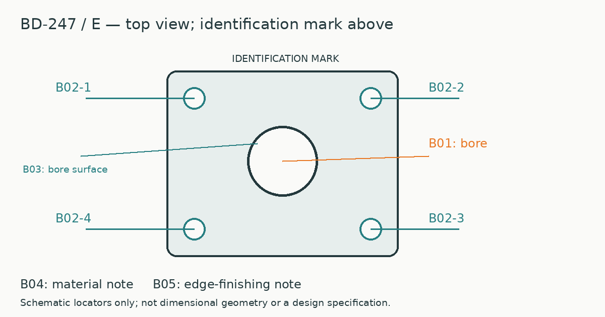
Schematic housing illustration—not to scale
For this fictional register, look down onto the mounting face with the housing identification mark at the top of the view. B01 is the central bore. The four B02 occurrences are upper-left, upper-right, lower-right and lower-left in that order. B03 addresses the indicated bore surface; B04 references the material note, and B05 references the edge-finishing note. These schematic positions locate evidence and do not define dimensional geometry.
| Schematic locator in the stated view | Characteristic | Accountability meaning |
|---|---|---|
| Centre | B01 | Central bore |
| Upper-left | B02-1 | First mounting-hole occurrence |
| Upper-right | B02-2 | Second mounting-hole occurrence |
| Lower-right | B02-3 | Third mounting-hole occurrence |
| Lower-left | B02-4 | Fourth mounting-hole occurrence |
| Bore surface callout | B03 | Roughness evidence |
| Material note | B04 | Material evidence |
| Edge-finishing note | B05 | Deburr evidence |
Occurrence accountability for HSG-247-A
For B01, 12.00 − 0.05 = 11.95 mm and 12.00 + 0.05 = 12.05 mm. For each B02 occurrence, 3.00 − 0.02 = 2.98 mm and 3.00 + 0.02 = 3.02 mm. The five assumed dimensional observations fall inside their respective numerical intervals. That comparison is not a product-release decision.
| Occurrence | Physical locator | Requirement | Applicable limits or criterion | Illustrative evidence | Review state |
|---|---|---|---|---|---|
| B01 · BD-247/E | Central bore | Bore 12.00 ±0.05 mm | 11.95–12.05 mm | Assumed observation: 12.00 mm | Inside numerical interval only |
| B02-1 · BD-247/E | Upper-left hole | Hole diameter 3.00 ±0.02 mm | 2.98–3.02 mm | Separate assumed observation: 3.00 mm | Inside numerical interval only |
| B02-2 · BD-247/E | Upper-right hole | Hole diameter 3.00 ±0.02 mm | 2.98–3.02 mm | Separate assumed observation: 3.00 mm | Inside numerical interval only |
| B02-3 · BD-247/E | Lower-right hole | Hole diameter 3.00 ±0.02 mm | 2.98–3.02 mm | Separate assumed observation: 3.00 mm | Inside numerical interval only |
| B02-4 · BD-247/E | Lower-left hole | Hole diameter 3.00 ±0.02 mm | 2.98–3.02 mm | Separate assumed observation: 3.00 mm | Inside numerical interval only |
| B03 · BD-247/E | Indicated bore surface | Surface roughness | Ra ≤1.6 micrometres | Suitable roughness evidence pending | Open; no roughness result |
| B04 · BD-247/E | Material note for HSG-247-A | Material grade note | Grade specified by drawing note | Material documentation comparison pending | Open; grade not established |
| B05 · BD-247/E | Edge-finishing note for HSG-247-A | Deburr note | Drawing’s deburr criterion | Visual evidence pending | Open; criterion not evaluated |
B03 needs suitable roughness evidence; a bore or hole diameter result cannot answer it. B04 remains open until the note-defined grade is compared with material documentation for this housing. B05 awaits visual evidence against the deburr criterion. Neither an invented material grade nor an unstated numerical burr limit fills those gaps.
Worked review record: BD-247/E
- Review scope: HSG-247-A, bound to BD-247/E throughout.
- Requirements accounted for: five, represented by balloons B01 through B05.
- Expected occurrence/evidence rows: 1 + 4 + 1 + 1 + 1 = 8.
- Rows with illustrative dimensional observations: five; rows with evidence pending: three.
- Review disposition: coverage enumerated, evidence incomplete; no release conclusion recorded.
The four identical assumed hole values are separate observations associated with the locators, not one value copied across a group. The evidence references must resolve to the underlying observations without relying on the order in which someone typed the rows.
06Worked revision decision: BD-247 from E to F
In this hypothetical case, BD-247 revision F changes only B01, the bore, from 12.00 ±0.05 mm to 12.10 ±0.05 mm. B02 through B05 retain their stated requirements. There are no other geometry, material, process or acceptance-criterion changes. The crosswalk below separates the changed requirement from unchanged characteristics; it does not authorize evidence reuse.
| Stable characteristic | Revision E requirement | Revision F requirement | Change classification | Evidence decision |
|---|---|---|---|---|
| B01 | Bore 12.00 ±0.05 mm | Bore 12.10 ±0.05 mm | Bore requirement changed | Open: assess applicable F evidence |
| B02; B02-1 through B02-4 | Four holes, diameter 3.00 ±0.02 mm | Four holes, diameter 3.00 ±0.02 mm | Unchanged | Assess applicability for each occurrence |
| B03 | Surface roughness Ra ≤1.6 micrometres | Surface roughness Ra ≤1.6 micrometres | Unchanged | Document applicability basis |
| B04 | Material grade note | Same material grade note | Unchanged | Document applicability basis |
| B05 | Deburr note | Same deburr note | Unchanged | Document applicability basis |
The revision F bore interval is 12.05–12.15 mm. The illustrative revision E observation of 12.00 mm is 0.05 mm below the new lower limit: 12.05 − 12.00 = 0.05 mm. This comparison does not transform an E-bound observation into evidence from an F part. Retain the original result, part identity and revision binding rather than relabelling the observation.
Worked decision record
For this example, BD-247-E-B01-OBS identifies the illustrative E-bound bore observation.
| Field | Recorded value |
|---|---|
| drawing_id | BD-247 |
| from_rev | E |
| to_rev | F |
| changed_characteristic | B01 |
| affected_occurrences | B01: single bore |
| evidence_refs | BD-247-E-B01-OBS; F evidence pending assessment |
| reviewer | Authorized revision-impact reviewer; assessment pending |
| decision | Open for revised bore; unchanged-characteristic applicability unresolved |
| rationale | Changed bore interval; E observation remains E-bound. Unchanged requirements alone do not establish evidence applicability. |
An authorized person assesses the bore change and determines which evidence applies to revision F. For any use of unchanged-characteristic evidence, record the basis, including relevant part identity and manufacturing context. Keep the revised bore decision open until applicable evidence is assessed. Route that assessment through change control; drawing approval and revision effectivity remain outside this article’s scope.
Annotation-only renumbering is a separate mapping exercise: an old-to-new display-label crosswalk can preserve the stable characteristic identity. Renumbering itself is not a product change and does not establish acceptance. If labels also change during the E-to-F update, record those label mappings separately from B01’s actual bore requirement change.
- Baseline EB01 bore: 12.00 ±0.05 mm.
- Retained evidenceThe 12.00 mm observation remains bound to E.
- Revision FOnly B01 changes: 12.10 ±0.05 mm.
- Characteristic crosswalkB01 remains B01; B02 through B05 are unchanged.
- Label aliasesRecord renumbering separately from engineering changes.
- Impact assessmentAn authorized reviewer determines applicable evidence for F.
- Recorded decisionPreserve rationale; numbering does not establish acceptance.
07Standards context and jurisdiction-specific applicability
IAQG 9102 is an aviation, space and defence first article inspection standard. Its general purpose is first article inspection; using ballooned drawings in another sector does not establish a universal medical-device mandate. Check the applicable contract and standard edition before treating aerospace conventions as project obligations.
The IAQG July 2023 Summary of Changes Revision B to C is official explanatory material, not legislation. It reports added Ballooned Design Characteristic and Ballooned Document terminology and clarification that FAI is not a product acceptance document. These statements do not themselves provide the definitions or reproduce the standard’s requirements.
The IAQG 9102B FAQ is historical Rev B guidance, not current Rev C requirements. Its F6 response permits any technique providing traceability from engineering to the FAI report; that flexibility statement belongs to the historical FAQ.
| Jurisdiction and product | Context to check | Ballooning boundary |
|---|---|---|
| Cross-jurisdiction aviation/space/defence contracts | Contract and adopted standard edition | Establish contractual scope |
| US human drugs | Current applicable drug rules | Do not presume aerospace applicability |
| US dietary supplements | Current applicable supplement rules | Assess product-specific documentation |
| US food | Current applicable food rules | Assess suitability for the characteristic |
| US medical devices | Current device rules and contracts | Do not infer a universal mandate |
| EU medical devices | Current device rules and contracts | Check scope independently |
| EU chemicals | Current applicable chemical rules | Do not substitute numbering for assessment |
This matrix is an applicability check, not a list of legal ballooning duties. Cross-sector use and local register design are practices unless a specific applicable obligation is identified. For medical-device implementation, connect that assessment to the organisation’s quality management system, rather than adopting aerospace terminology as a legal conclusion.
08Exchange register data and recover exceptions
Treat exchange between drawing annotations, the characteristic register and inspection outputs as a mapping task. The annotation locates the requirement; the register identifies its applicable occurrences; measurement or inspection outputs provide referenced observations. A practical exchange specification carries stable characteristic identifiers, drawing revision, occurrence identifiers, units and evidence references together. Preserve this characteristic-to-result relationship through attributable recording, rather than relying on row position.
Define source-to-destination field mappings explicitly and review imported values before using them. Check that identifier lengths preserve occurrence suffixes, decimal separators retain their intended meaning, and unit conversions preserve both value and unit. Retain original values alongside justified conversions. Hold entries with missing revision context for clarification; do not infer revision from the destination filename.
Exception record: a complete count, incomplete coverage
In this hypothetical BD-247/E import, eight rows contain B02-3 twice and omit B02-4. All other expected identifiers appear once: there are seven distinct occurrence identifiers against eight expected occurrences. Imported observations M03 and M04 both carry B02-3.
| Field | Decision record |
|---|---|
| register_key | BD-247/E |
| duplicate_occurrence | B02-3 |
| missing_occurrence | B02-4 |
| affected_evidence | M03 and M04; occurrence assignments ambiguous |
| recovery_action | Quarantine both duplicate entries from coverage credit; preserve originals; investigate assignments |
| reviewer | Assigned inspection reviewer; decision pending |
| resolution_state | Unresolved; B02-4 remains open |
For recovery, compare the original measurement source with the physical feature locator and establish which occurrence each observation actually belongs to. Correct the mapping only when that comparison justifies it, documenting the basis and retaining the original assignment. If identity remains unresolved, obtain identifiable replacement evidence through the inspection workflow. Then reconcile expected identifiers, distinct imported identifiers and evidence assignments again. Do not relabel a duplicated result merely to fill the gap: matching row totals does not establish occurrence coverage.
09Recognize coverage failures before review
A complete-looking register can still connect the wrong feature, observation or document to a requirement. These diagnostic controls are suggested characteristic-accountability practices, not universal inspection mandates. They test whether an entry supports its assigned characteristic, rather than whether every row contains something.
| Observed symptom | Why coverage is unreliable | Targeted control |
|---|---|---|
| A leader ends between adjacent features. | Balloon proximity does not establish which physical feature the result describes. | Resolve the physical locator using the view, feature boundary or explicit location reference; confirm the result addresses that feature. |
| Evidence comes from the wrong verification stage. | The characteristic may not yet exist in its assessable condition, or later operations may alter it. | Identify when meaningful examination is possible and assess subsequent operations before relying on the observation. |
| A material document is attached without an instance link. | The document may describe a different material lot or component. | Verify the relationship between the document, relevant material instance and inspected item. |
| A qualitative note has only a pass entry. | The conclusion conceals what was examined and how the note was interpreted. | Retain the criterion, observation and responsible person's assessment. |
| A numerical result lacks units or measurement context. | Comparison may depend on an unstated unit, datum, condition or method. | Resolve missing context before interpreting the result against the requirement. |
An evidence gap leaves conformity undetermined; a demonstrated nonconforming result establishes that a requirement was not met. Route gaps to the responsible inspection or technical owner for clarification or examination. Route demonstrated failures to authorized quality personnel through nonconforming-result handling, preserving the distinction in the register.
10Resolve crowded leaders and overlapping note applicability
A dense drawing can make leader placement ambiguous even when the register itself is complete. Choose an uncluttered detail view or a separately keyed feature map when two leaders would cross. The identifier is useful only if a second reader can resolve the same feature without asking the person who placed it. Keep the underlying design document unchanged: the accountability overlay provides references, not revised engineering requirements.
When one note applies to several surfaces
A general finish note can apply to more than one face, while a local callout can override it at one identified surface. Extract both statements and record the interpretation question instead of assuming that a nearby balloon narrows the general note. Ask the authorized design function to identify the applicable scope where the source is unclear. Retain that clarification with the affected characteristic entries and the drawing revision it addresses.
When two balloons seem to address one requirement
Check whether they represent separate occurrences, two different criteria on the same feature, or a duplicate extraction. Size and position can both govern a hole without being the same characteristic. Conversely, two copied leaders pointing to the same size callout do not necessarily create two independent requirements. Resolve the relationship and preserve a cross-reference before eliminating a row; record the reason so an apparent numbering gap remains intelligible.
For inaccessible boundaries, retain a saved viewing direction and a description of the feature extent. A leader placed beside an edge can refer to a face, an edge treatment or a profile boundary. The annotation should direct the reader to the controlling callout, not supply a guessed interpretation. Escalate unresolved feature boundaries before assigning an evidence method. Track ownership of that decision with a distinct configuration specification reference.
Frequently asked questions
Q.Can a model-based definition be ballooned instead of a paper drawing?+
Yes. In common inspection-planning practice, identifiers can be associated with model annotations and features rather than paper callouts. The useful test is whether another person can locate the same requirement in the identified model revision and connect it to its register entry. Include saved views or feature references where geometry alone is ambiguous. Account separately for requirements held in associated notes or specifications. This is a practical application of requirements traceability, not a claim about automatic CAD extraction. Preserve the applicable model revision through document control.
Q.Can suppliers and customers use different characteristic identifiers?+
Yes, provided the agreed reporting arrangement preserves an unambiguous crosswalk. A practical crosswalk records both identifiers, the drawing revision, the requirement location and any occurrence suffix. Avoid matching by nominal dimension alone: unrelated features can share the same size. Where one customer identifier corresponds to several supplier rows, show every relationship explicitly. Before exchanging results, agree which identifier set appears in the report and how later additions or renumbering will be communicated. Keep actual incorporated identity separate in as-built configuration.
Q.Does measuring one hole justify leaving the other three blank?+
No—not as evidence that all four holes were measured. In the hypothetical BD-247 register, B02-1 through B02-4 identify separate occurrences of the same diameter requirement. A result for B02-1 does not describe the others. If an applicable inspection plan permits sampling, record the sampled occurrence and the basis for the remaining coverage instead of leaving unexplained blanks. Keep the distinction between an unmeasured occurrence and a missing inspection record explicit; they call for different follow-up.
Q.Can one material certificate support several characteristic rows?+
Yes, as a practical evidence arrangement, if the certificate addresses each referenced requirement and is linked to the material used for the inspected item. Identify the relevant certificate entry for each row rather than copying a general accepted status across the register. A grade statement does not, by itself, establish a separate finish or deburring requirement. Shared evidence can reduce duplication, but each characteristic still needs its own intelligible connection to the information supporting it. Match supplied material identity through incoming inspection.
Q.What if an internal feature becomes inaccessible after assembly?+
Plan its evidence capture while the feature remains accessible. A practical register identifies the manufacturing stage, the part or subassembly identity, and the result reference before assembly conceals the feature. Also assess whether later operations could alter the measured condition; an earlier measurement may not represent the finished state. Link this planned in-process check to the final characteristic entry. If the opportunity has already passed, seek an authorized technical assessment rather than filling the row from assumption.
Q.Can a basic dimension be excluded because it has no plus-or-minus tolerance?+
Not solely for that reason. In common drawing interpretation, a basic dimension can establish theoretically exact geometry whose permitted variation is controlled elsewhere, such as by an associated geometric tolerance. Trace that relationship before deciding how to represent it in the register. A useful entry identifies the controlling requirement and the evidence evaluating it, rather than inventing a standalone size tolerance. If the relationship is unclear, obtain design clarification instead of silently treating the dimension as informational.
Q.Can a balloon cover both a local callout and a general note?+
Only if the register keeps the different criteria and their applicability intelligible. A local size requirement and a general surface or finishing note may need different evidence even when they affect the same feature. Record the controlling source for each criterion instead of using one accepted status for both. Where the local statement appears to override the general note, obtain an authorized interpretation and retain it with the drawing revision. Balloon placement alone cannot settle that engineering question. Applicability selection is distinct from revision effectivity.
Q.How should a result exactly on a tolerance boundary be assessed?+
Apply the agreed decision rule rather than treating the displayed value as automatically acceptable or unacceptable. A practical assessment considers whether the boundary is inclusive, the unrounded result where available, measurement uncertainty, and any specified guard band. Rounding can make a value appear exactly on a limit while concealing its position relative to that limit. Record the rule used and the resulting decision. If no rule has been established, refer the case for authorized technical resolution.
Primary sources
Want to see how Ballooned Drawing could fit into your own records and workflows? Explore the related V5 pages or talk to our team about what applies to your operation.